AIV Testing at RAL

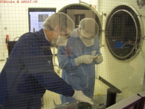
Wouter PA3WEG (on the right!) working in the RAL Space cleanroom before placing the spacecraft into the vacuum chamber
During the week starting 18 July, we performed temperature testing and themo vac testing. We were very kindly offered the facilities to do this by the AIV section at the Rutherford Appleton Laboratories, at Harwell, near Oxford. We are extremely grateful to them for helping and advising us. The boards we tested were our ‘Engineering Models’ (EMs) which are just about identical to those that will fly. Below are some pictures of the facilities, and the team.
Part 1 of this report is below, and covers the first part of the week – testing in air
Part 2 of this report is below, and covers the second part of the week – thermo vac chamber.
Part 3 Vibration
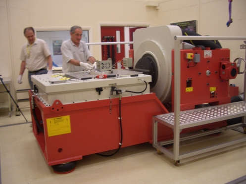
Having subjected our ‘stack’ to extremes of heat and cold in and out of vacuum the previous week, it was with some trepidation that members of the FUNcube team arrived at the RAL Vibration test facility on Monday 25 July 2011. Our commercial partner, ISIS Bv had prepared a document with the sorts of tests and loads we should put on the stack, and this had already been reviewed by the team at RAL Space.
We were met by the head of the Vibration Test facility, Dave Rippington, who was extremely generous in answering all our questions including the rather naive ones! The members of the FUNcube team were Graham, David and Jim.
There is not sufficient space here to detail all the tests we did, but the plan was to subject the stack to ‘sine sweep’ from 8 to 100 Hz at 4g, a ‘Quasi-Static’ test with amplitude 11g at 20 Hz for 10 cycles, and finally a ‘Random’ test at various frequencies between 20 and 2000 Hz at 7.88 g rms. Before the first test, and between each of the tests a ‘sine survey test’ at a mere .5 g from 5Hz to 2000 Hz would be conducted. The idea of this test is to characterise the stack, and also determine if there had been any significant changes during the previous test.
Each of the above tests would be carried out in each of the three axis’s, X, Y and Z. We were mostly concerned about the Z axis series of tests, as this is perpendicular to our pcbs, and hence likely to put maximum stress on them. Our pcbs were mounted in the Engineering Model (EM) structure along with a PMASS board and BOB from ISIS, and our own EM EPS.
The stack in turn was mounted inside a test POD (again on load from ISIS). The POD is similar, but not exactly the same, as a flight version of a 1U POD. The RAL personnel were fascinated with the spring (see picture) in the POD, and expected it to ‘scream’ during the tests! The POD in its turn, was mounted on a specially made round adapter plate, which would be bolted to the vibration table itself.
We were very nervous least we break the stack. We wanted to have it in a working condition for the AMSAT-UK Colloquium at the end of the week, so we could demonstrate the reception of the tlm and the transponder to the delegates. We planned to remove the stack from the POD after each sets of tests in each axis, and functionally test it by connecting a spectrum analyser, decoding the tlm, and testing the transponder. During the tests, unlike, the thermo vac tests, we had the proper lithium batteries mounted on the EPS as they would be in flight.
On our pcbs, we had previously glued the large components, eg the air spaced coils on the PA, to the pcbs using ‘Space Glue’, actually Scotchweld type 2216. On the previous Friday, after the thermal-vac tests, we had attached the batteries, removed the thermo couples, and glued on the accelerometers. We had accelerometers as near as possible to the centre of each of our three pcbs, the EPS, and the PMASS. We also fitted one to the structure of the stack, and to the outside of the POD. While reassembling the stack, we applied more of the ‘space glue’ to the fasteners holding the stack together; we didn’t want anything falling off during the tests.
So the testing proceeded, and some of the results are shown below. It was fascinating to watch the vibration machine subjecting our stack to the various forces set up by Dave Rippington. Some were alarmingly vigorous, and for some, ear defenders were the order of the day. We were very happy indeed when the sine survey tests showed only a little variation in ‘signature’. We noted that any significant resonance below 100 Hz was a definite no-no for launching, and we were content to see that, in general, resonances were above approx 250 to 300 Hz.
FUNcube AIV Testing – A High Sine Z axis test more videos.
We were absolutely delighted when we removed the stack for the last time (after the Z axis test), activated the telemetry and transponder and found that it was still fully functional. Some of our boards had been measured as having been subjected to over 60g!
It was a really stressful day for the team, watching the FUNcube hardware being subjected to forces that are actually greater than it will experience at launch, is not something to be recommended for the faint hearted, however the eventual success made it very worthwhile.
FUNcube AIV Testing – A look round the facility, plus interviews with Graham and David after the tests more videos.
Part 2 of the testing at the Rutherford Appleton Laboratories was the use of the Thermo Vac chamber. In this chamber, not only would the stack be subject to wide variations of temperature, from -20 degs C to +70 degs C), but it would also be subjected to low pressure, as expected in space, throughout the testing. The pressure achieved was approximately 3.6 x 10e-5 millibars, a reasonable approximation to that expected after launch.
We loaded the stack into the chamber on Tuesday evening, and it was left overnight to stabilise overnight. We had detailed discussions on whether or not to leave the side panels attached to the stack. We realised that the mechanism of heat transfer in the thermo vac chamber was different to that in the air chamber, in the former is would be solely by radiation, and in the later by both radiation and convection. We decided to leave the panels off, as we thought this would assist the radiation process.
On Wed morning we saw that the ambient temperature inside the chamber was a steady 40 degs C. Whilst in the chamber the stack was powered and we were able to receive the telemetry (tlm) transmitted by the stack, hence we could calibrate the tlm sensors during the forthcoming tests. The thermo couples were connected to the RAL logging system, and were located at the following positions: the RF pcb, the PA PCB (right on top of the final amplifier device, expected to get the hottest), the CCT pcb, the stack structure, and finally on the large metal plate on which the structure was mounted, just underneath our stack.
After a few hours, the temperatures recorded were RF 58.27, PA 58.77, CCT 53.09, and structure 50.5. We were happy that the stack was still working OK, and we were able to command it from outside the chamber by using the uplink commands. We then decided to cool the stack to approx -15. By approx 3pm, the RF board was at -8 degs C, and all systems were working OK. We slowly went colder, and carefully monitored the down link, and as had happened during the in air tests, there was a sudden shift of 20 KHz or so in the downlink transmit frequency at about -10 degs C. We assumed that this was due to a change of mode of the crystal vibration.
We decided that during the night we would cycle the temperature back up to approx 65 degs C, and then back down to approx -10 degs C.
On Thursday, all was still well with the stack, and it was working nominally. We next decided to put the PA into a high power mode, and careful monitor the differences in temperature between it and the RF board. We measured the power output of the transmitter as 260mW in its continuous, test carrier wave, mode. We found that the PA board never got warmer than the RF board by approx 3 degs. This was good news, as it meant that the PA device was, to a certain extent, thermodynamically coupled to the RF board, and dissipating some of its heat there. In contrast the CCT board, was always significantly cooler than the RF board by something like 5 degrees.
We continued temperature cycling during the rest of the testing period between about -10 and +65, with a ‘hold’ at the high and low extremities af approximately an hour. The rate of change of temperature was much faster than we would expect in space. We made a total of nearly 5 hot/cold cycles during the time we were in the chamber, and were VERY PLEASED TO NOTE that at the end of the testing the stack was still fully functional, although, it must be said that we did find one or two things that need fixing, eg the freq jump at low temperature.
FUNcube AIV Testing more videos on Vimeo here .
Friday morning was spent removing the stack from the thermo vac chamber, removing the thermo couples, attaching accelerometers , and returning the stack to the POD, ready for the vibration testing on Monday.
We are VERY grateful to The Rutherford Appleton Laboratory for the use of their facilities and invaluable advice from their engineers.
AIV Testing – Part 1
In summary (as at Wed 20 July) we have determined that the stack operates down to a temp of minus 10 degs C and up to +60 degs C and survived storage at -30 and +70. These results were obtained by the use of a temperature controlled oven in air. Yesterday evening, Tuesday, we transferred the stack to a thermo vacuum chamber, and are continung testing.
We are aiming to complete the thermo vac testing by Friday morning, leaving the rest of Friday to apply glue to the structure, and mount it in its ‘POD’ ready for vibration testing on Monday.
The temperature is measured by the means of thermocouples which are mounted in different places on the ‘stack’, one on the PA final amplifier device, one the the microproccessor of the CCT Board, one on the RF board near the rx local oscillator, and the forth one on the structure. When in the air the readings from the termocouples are noted down manually. In the termo vac chamber these reading are logged automatically once per minute.
We are also logging all the telemetry sent by the stack, via a FUNcube dongle, so in this way we will be able to calibrate some of FUNcubes temperature sensors.
Comments are closed.


Have you done any total radiation dose or single event tests?
What happened?
Hi Tony. Short answer is no, we havnt. But we have been thinking about it. Our thought is that we will be at too lower an altitude for us to be effected much by radiation. If anything we might glue some scrteening material over the vunlerable chips, eg MCU