PA Board
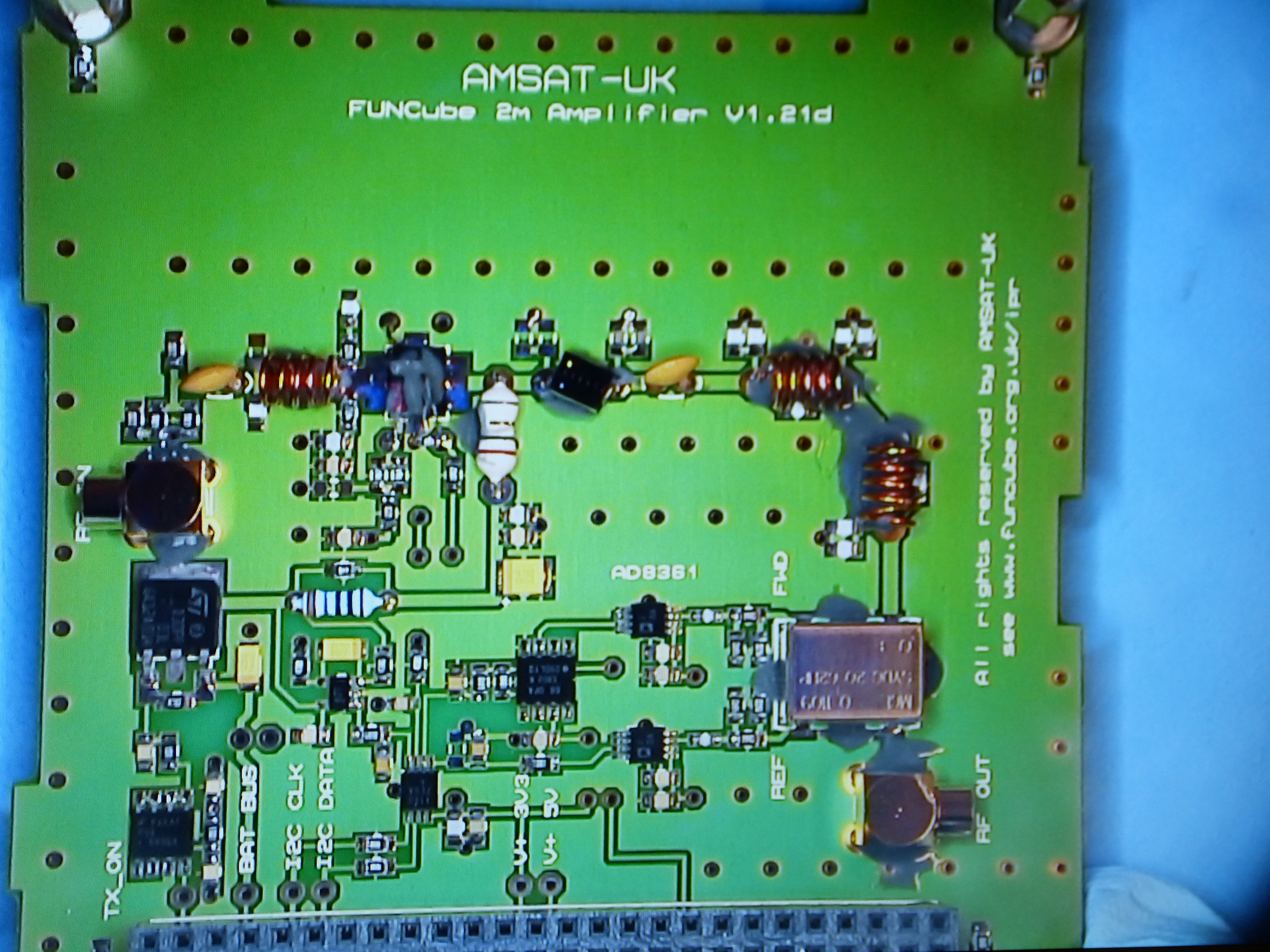
The picture below was taken at the end of October 2010, and is of the prototype Power Amplifier (PA) board in a ‘very nearly’ completed state. There are a few components to add, the values of which must be determined as they are installed – a time-consuming process. Thanks to David, G0MRF, for these pictures!

The power amplifier board increases the power level of the beacon and transponder signals. The signals, at 145MHz, arrive from the RF board with a maximum power of 30mW or +15dBm. These low level signals are amplified to 400mW (+26dBm) before being sent to the transmit antenna. The RF amplifier is a single stage class AB amplifier using a Mitsubishi RD02MUS1 power MOSFET. The amplifier uses the unregulated battery voltage which, in normal use, will vary from 6.8 to 8.2 Volts. The amplifier is followed by a low pass filter which removes frequencies above 160MHz. The filter includes traps that add additional attenuation to the third harmonic, which is close to the command and transponder UHF input frequencies.
In addition to the RF amplifier, the PA board contains four sensors that gather data for the satellite’s telemetry. The sensors are:
Supply current to the PA transistor (mA)
Temperature of the power amplifier transistor (degrees C)
Forward RF power (mW)
Reverse (or reflected) RF power (mW)
The 4 channels of telemetry are sampled by a Maxim 4 channel A-D converter and then sent to the CCT board via an I2C interface.
The completed flight model power amplifier board is pictured below.